01 / EXHIBITIONS
Exhibition stands & graphic panels
Compare arm lights, beam angles and fixings for trade show booths, modular frames and exhibition wall graphics.
Plan exhibition lighting →Sourcing lighting for a trade show booth, exhibition stand, illuminated sign or lightbox? Email our team for product selection, samples, wholesale quotations and OEM, ODM or private-label requirements.
Send product links, drawings or specifications by email. We will review your requirements and discuss the product configuration and quotation with you.
Minimum order: 20 pcs
Volume pricing: Lower unit prices at higher quantities
Samples: Available; configuration, cost and shipping confirmed with your enquiry
Standard lead time: 12–18 days
Custom cooperation: OEM, ODM and private label
Confirm the production schedule for your quantity and configuration. Custom project timing and transit time are agreed separately.
Share the product link or model, estimated quantity and destination country. Add any available drawings, mounting details, colour temperature, voltage, connector or branding requirements.
For exhibition arm lights, include the frame or mounting details. For LED light box modules, include the illuminated dimensions and installation depth. Our team can help clarify the specification as your project develops.
DISPLAY & EXHIBITION LIGHTING
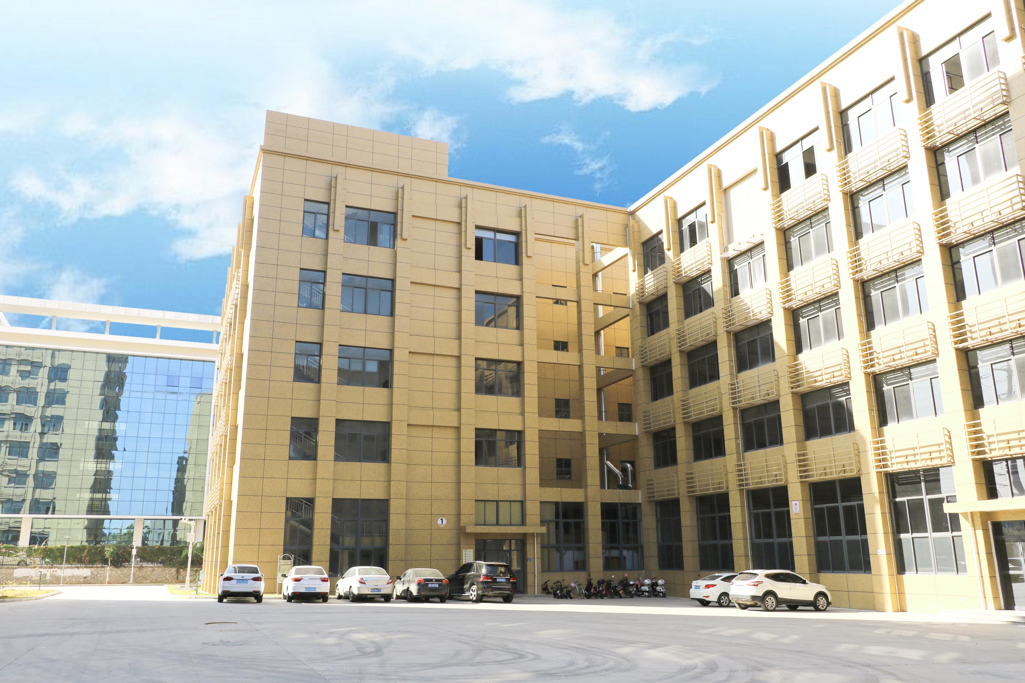
Manufactured in Xiamen since 2007. LED display arm lights, rigid lightbox modules and lighting components for exhibition builders, sign makers and wholesale distributors.
FEATURED PRODUCTS
Explore exhibition arm lights and LED lightbox modules for your next project.
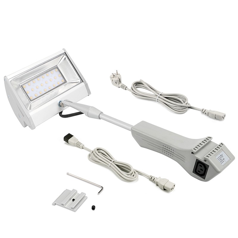
5500 lm · 60° beam · AC 100–240V
View product →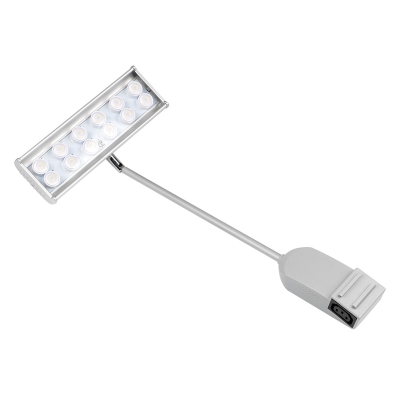
3500 lm · 12 LEDs · Three-pin linking
View product →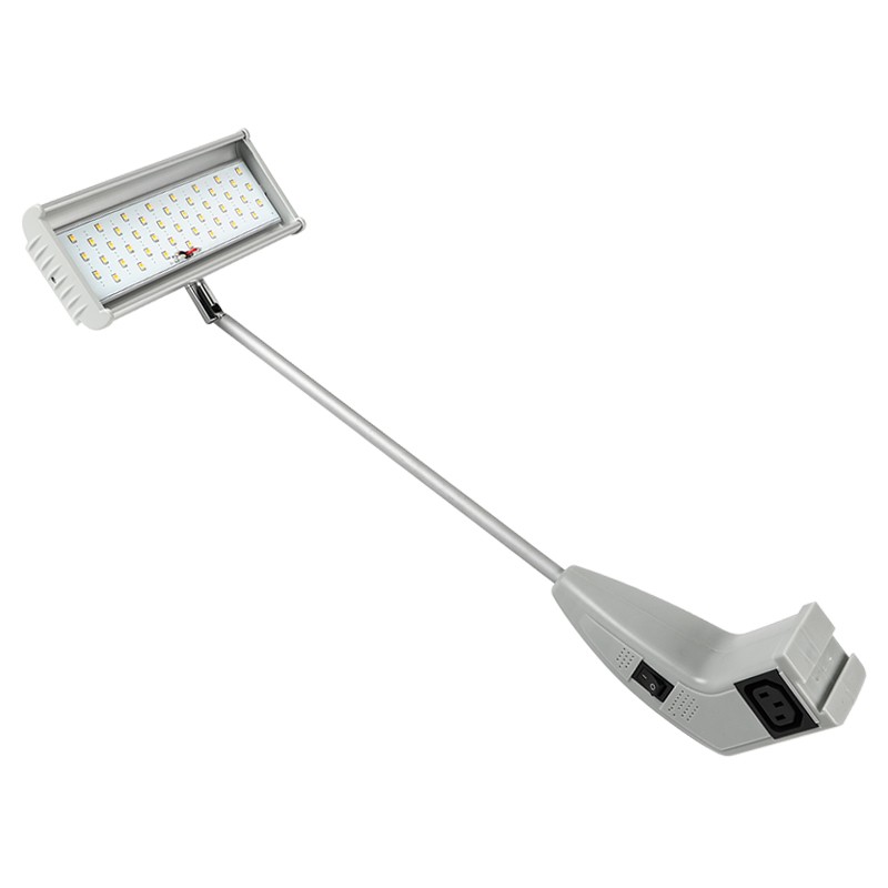
2500 lm · 120° beam · Silver finish
View product →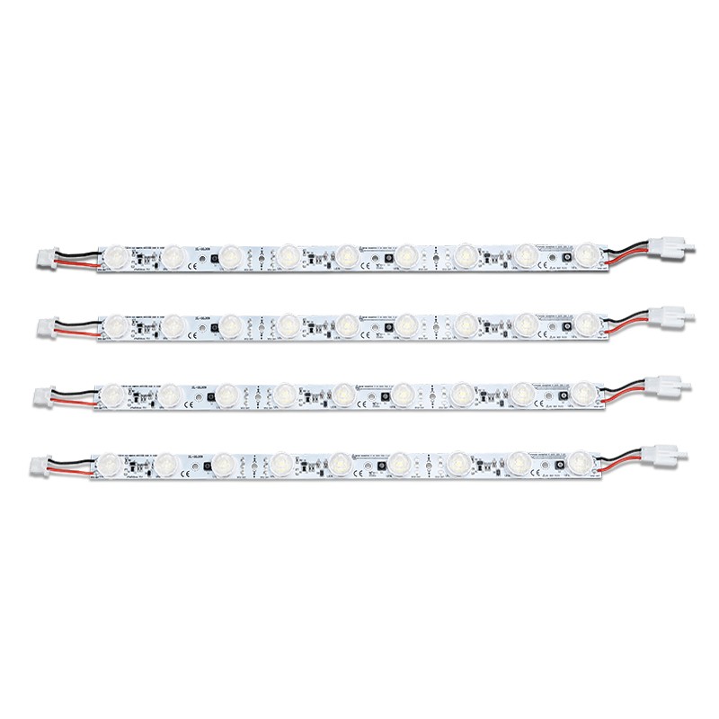
1000 lm · Warm, neutral or cold white
View product →
DC 24V · 5 LEDs · 15 × 45° optics
View product →
DC 24V · 1000 lm · 15 × 45° optics
View product →Also explore LED ladder lights for lightboxes and display lighting mounting accessories.
APPLICATIONS
Lighting selection starts with the structure, the illuminated surface and the installation space.
01 / EXHIBITIONS
Compare arm lights, beam angles and fixings for trade show booths, modular frames and exhibition wall graphics.
Plan exhibition lighting →02 / LIGHTBOXES
Compare edge-lighting and backlighting layouts using the cabinet depth, graphic dimensions and module configuration.
Compare lightbox layouts →03 / SIGNAGE
Specify module dimensions, voltage, white-light options and installation details before selecting a sample.
Specify LED modules →MANUFACTURING & DEVELOPMENT
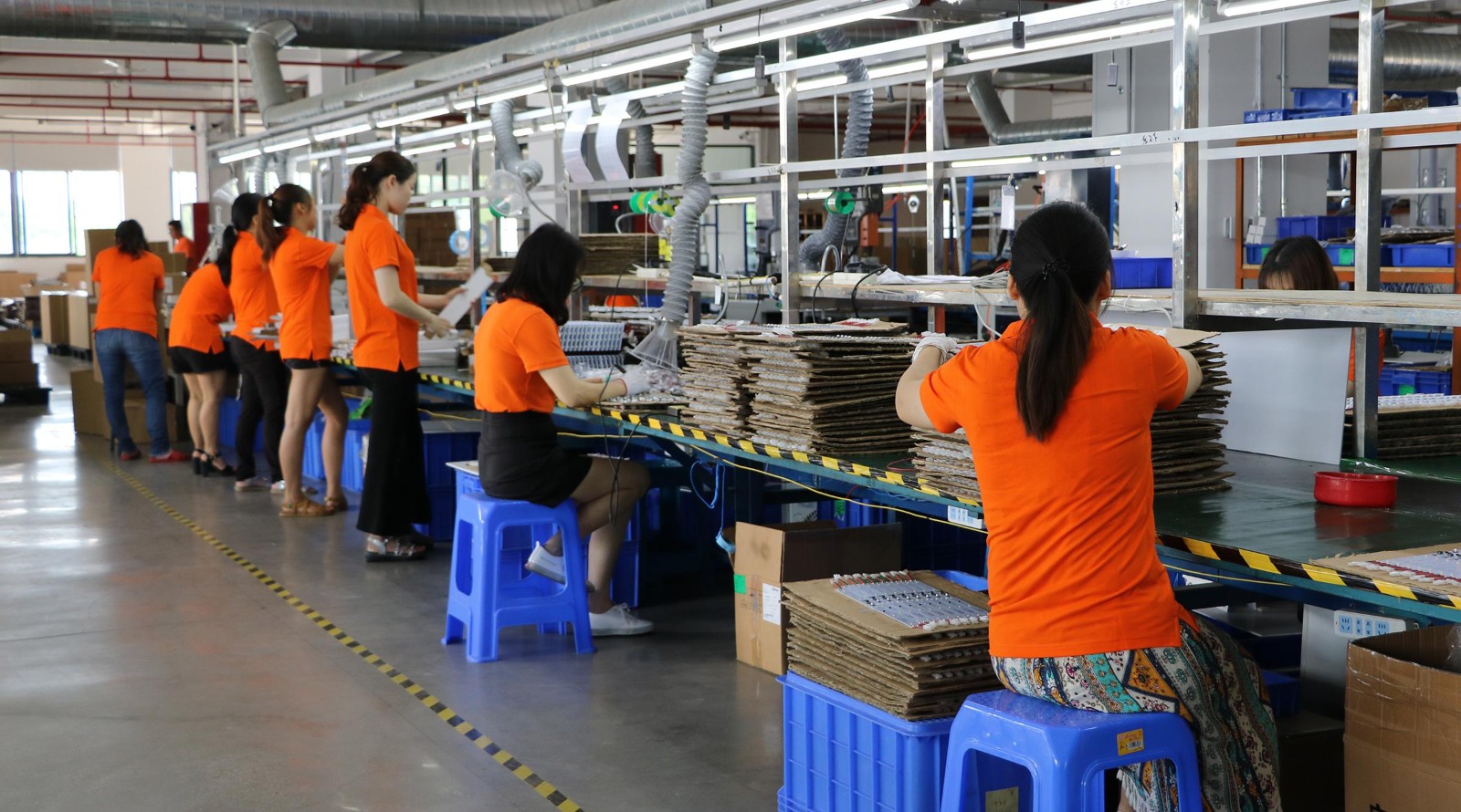
Our 3,000 m² manufacturing facility brings together four production lines and an 85-person team. Production, R&D and testing facilities support the LED display lighting range.
Wholesale purchasing and OEM, ODM or private-label projects can be discussed around your application, specification and target quantity.
Inside our manufacturing operation →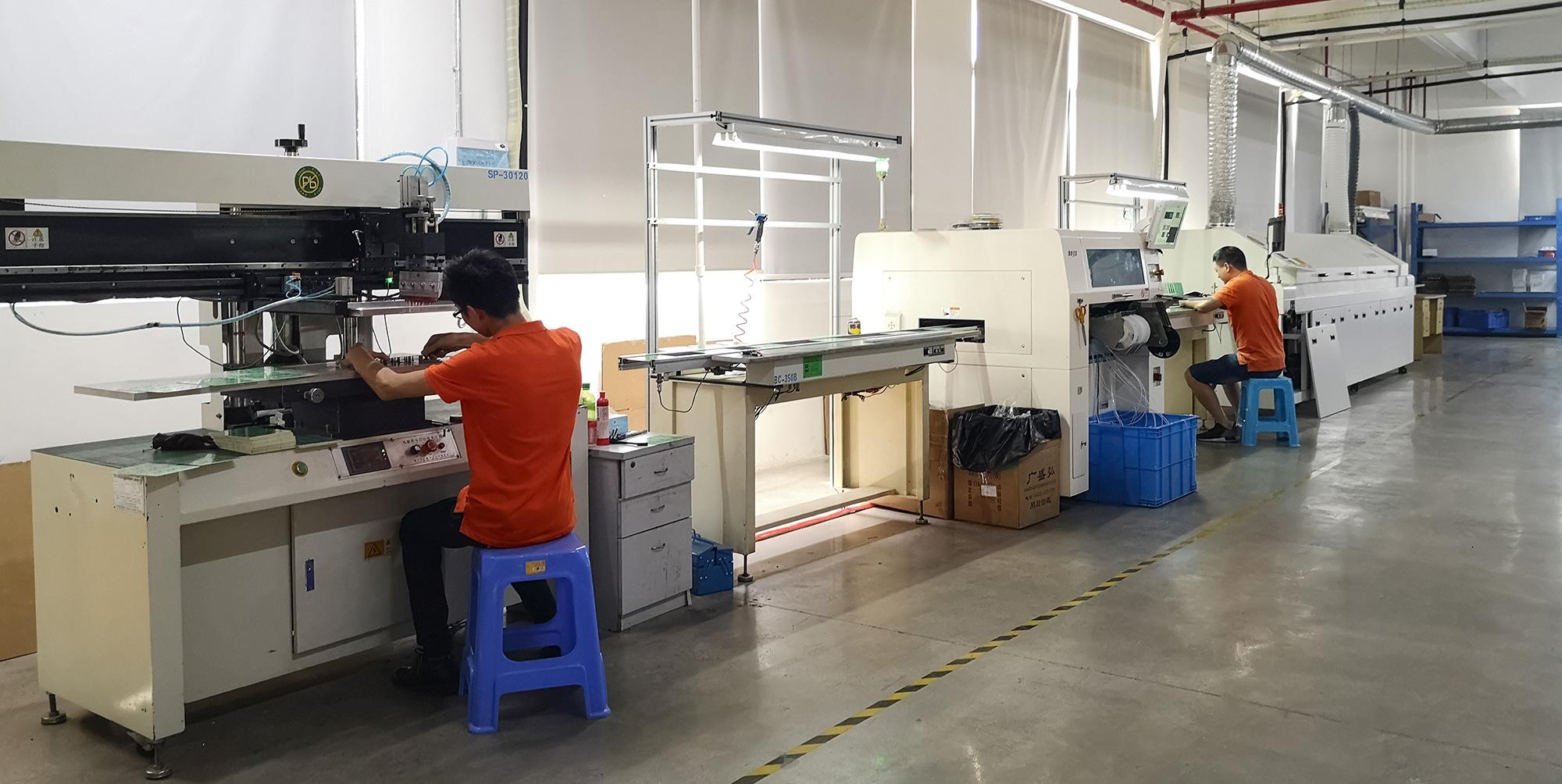
SMT workshop equipment for LED lighting production.
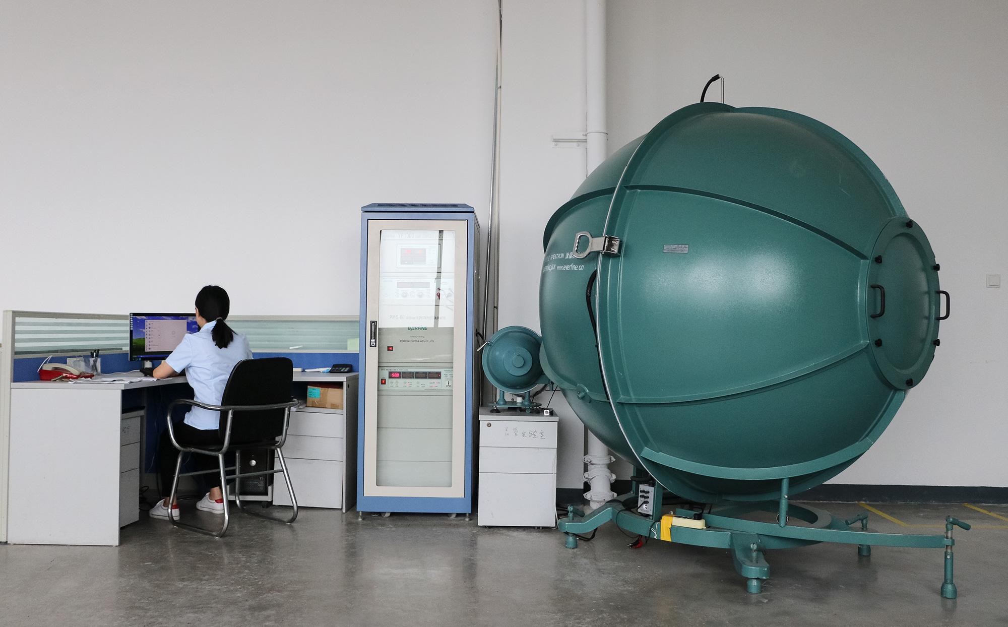
R&D facilities and lighting measurement equipment.
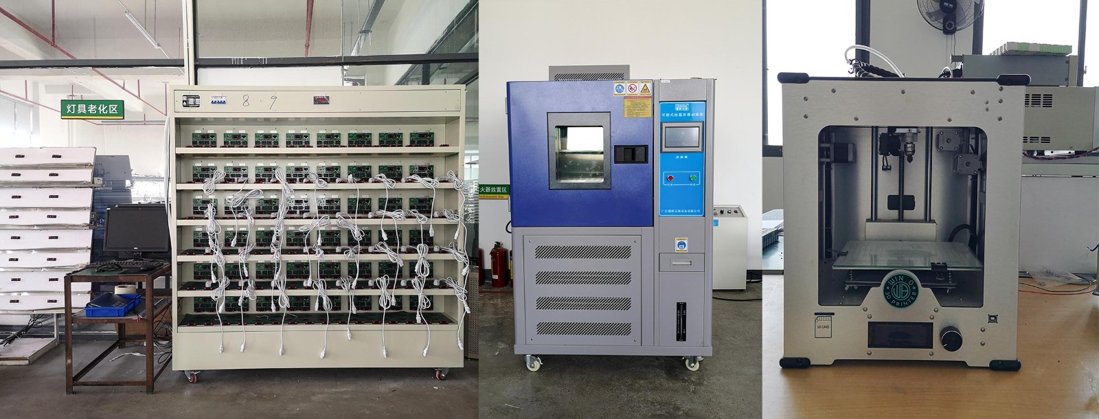
Aging-test area and equipment used in product development.
TECHNICAL & PURCHASING RESOURCES
Practical guidance for mounting, electrical configuration, sample evaluation and custom supply.
Compare clamps, frame sliders and mounting plates against your panel or frame details.
Read the mounting guide →Review the light appearance, dimensions, fixing and power connection before a bulk order.
Evaluate a lighting sample →Prepare your specification, branding requirements and target quantity for a custom project brief.
Prepare your project brief →Send the product links or models, quantity and destination. Add mounting, electrical or branding requirements where relevant.
Contact our sales team →Emailsales@displayarmlight.com
WhatsApp+86 189 5001 1097 →
Wholesale orders from 20 pcs · Samples available · Standard production lead time 12–18 days · OEM, ODM & private label. Confirm the configuration and schedule with your quotation.
A lightbox with bright spots or dark edges needs a layout check before a new module order. The visible result depends on the light-source positions, lens direction, enclosure construction and display face working together.
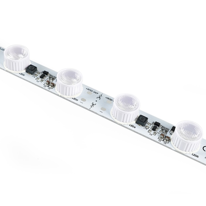
Start by documenting the symptom and the existing assembly rather than changing only the wattage.
This checklist helps sign makers and display fabricators prepare a useful sample comparison. It separates possible optical and construction issues from connection or colour-version questions. The aim is to identify which specification should be reviewed, then assess the proposed component in the actual display.
Photograph the full illuminated face and its unlit construction. Mark where the symptom appears, and record the model, white-light version, bar positions, lens direction and enclosure depth. Keep the same graphic or diffuser for the first comparison so that a change can be assessed against a clear baseline.
| Observed symptom | What to check | Useful sample comparison |
|---|---|---|
| Bright points or bands | Lens direction, source-to-face space, face material and bar positions | Compare a revised position or orientation using the same face material |
| Dark edges or corners | Frame obstructions, perimeter positions, fixing clearances and graphic tension | Assess the whole edge and corner after a documented layout change |
| Uneven brightness along the assembly | Connection integrity, polarity and approved feed/cable arrangement | Review the specified wiring configuration with the matching component sample |
| Different white appearance between areas | Exact model, ordered white-light version and mixed component references | Compare the proposed same-specification sources behind the actual graphic |
| Acceptable result with one face, different result with another | Printed graphic, diffuser or face construction | Test the intended production material in the same enclosure |
For a compact edge-positioned test, SL-BL031 measures 157 × 24 × 16mm, with a 24V DC input and 10 × 40° optics. SL-BL005-100 offers a 360mm, 10W lens bar with 15 × 45° optics and documented white-plug or DC-connector versions. Compare their positions and connection requirements with the intended frame.
For a longer lens-bar option, SL-BL029-120 is 517 × 27 × 16mm, 12W, 24V DC and 15 × 45°. For a backlighting comparison, SL-BL052-6L-140 is 319mm with 20 × 60° optics; SL-BL085-12L is 710mm with 14 × 47° optics. These figures describe different components, rather than a universal remedy for an uneven face.
If an area is dimmer than expected, include connection photographs and the power-unit label with the enquiry. Confirm the selected source input, polarity, connector version and approved feed arrangement before comparing new layouts. A wiring review should follow the documented component configuration and the project installation requirements.
The selected white-light range also belongs in the sample record. For example, SL-BL029-120 lists 6000–7000K, while the 319mm module provides four ordering ranges. Compare matching versions when evaluating appearance; a common bar length or similar lens does not establish a common white-light specification.
Use the intended frame, graphic face, fixings and cable route. Agree the proposed test change in advance, then compare the centre, edges and corners under consistent viewing conditions. Record the result alongside the component specification so the approved assembly can be repeated.
Share the enclosure drawing, depth, display-face material, symptom photographs and module quantity with our team. We can help define the component shortlist and quotation for the sample. Where a standard source does not fit the project, OEM enquiries may include circuit-board design, terminal processing, dimensions and fixing devices.
Open the product detail for its complete specifications, pictured options and ordering configuration.
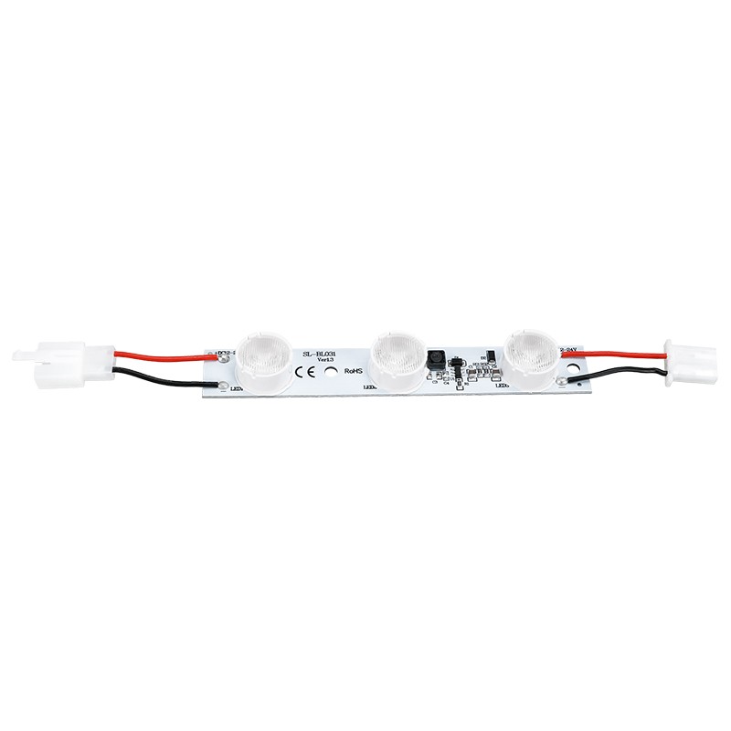
Compact 157mm edge-source example for an orientation and frame-clearance comparison.
View specifications & options →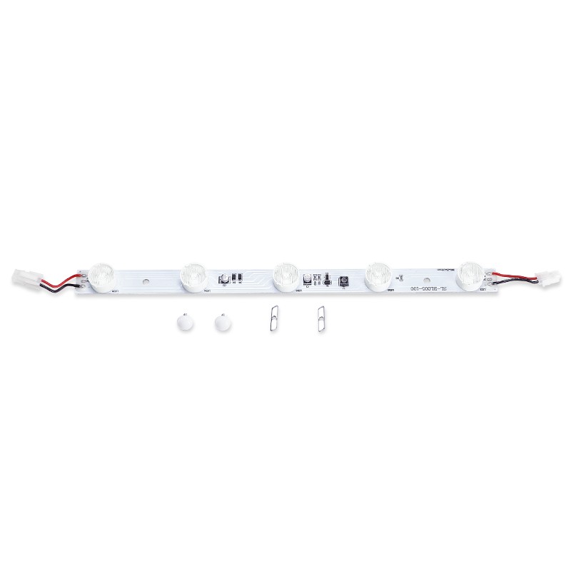
360mm 15 × 45° lens bar with connector-version choices for a layout sample.
View specifications & options →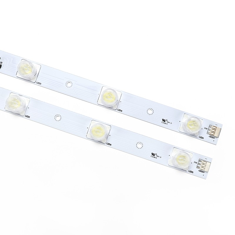
517mm 15 × 45° lens-bar example with a defined 6000–7000K specification.
View specifications & options →319mm six-LED backlighting option with 20 × 60° optics.
View specifications & options →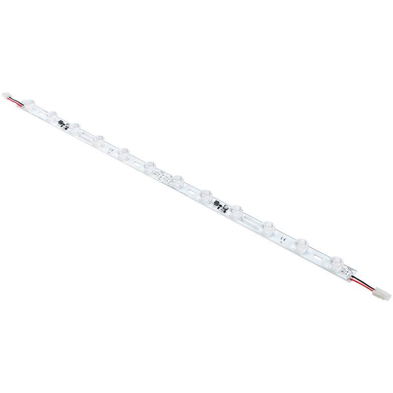
710mm twelve-LED backlighting option with 14 × 47° optics.
View specifications & options →Output alone does not determine the finished appearance. Check lens direction, mounting positions, enclosure depth and face material, then evaluate the proposed source in a representative sample.
The listed model specifications do not establish one universal spacing or depth rule. Provide the actual enclosure and face details so the layout can be assessed for the project.
First identify the existing layout and the space available for mounting, wiring and the display face. Compare a suitable sample arrangement for each feasible approach instead of assuming that changing the layout name resolves the symptom.
Share the details you already have. Product links, a drawing or installation photos are useful starting points.
Full-face symptom photographs and a photograph of the internal layout
Internal dimensions, depth, frame section and fixing obstructions
Graphic, diffuser or display-face specification
Existing model, white-light version, module positions and lens direction
Power-unit label, connectors, cable route and proposed sample change
Samples and wholesale supply are available. Standard orders start from 20 pcs, with a usual production lead time of 12–18 days. Confirm the configuration, quantity and schedule with your quotation; OEM work is scoped separately.
sales@displayarmlight.com · Drawings and product references are welcome.
Contact: CODY
Phone:
Tel:
Email: sales@displayarmlight.com
Add: Huli Avenue, Xiamen China
We chat

 English


